Discovery steps
To perform the network topology discovery follow the instructions
in the tabs "Step 1", "Step 2", "Step 3".
Step 1

1. Specify the ranges of the IP addresses for switch discovery.
For example: 192.168.0.* 192.168.0.100-200 172.16.200-255.*
Set SNMP access parameters for each range ("read community string"
or user/password in case of SNMPv3).
To duplicate the range select this range and click "Add the range" button.
You can add a device to the map even it does not support SNMP.
For this, instead of IP range enter IP address of this device with a "+" in the first position.
Example: +192.168.0.1 Also enter any name in community string field.
To exclude device from a scan add new IP range and enter IP address of this
device with a "-" in the first position. Example: -192.168.0.99
You can enter any comment in the community string field.
2. Discover the switches
Click "Run device discovery"
Discovered switches will be added to the list of SNMP devices (see table right).
Turn on the option "Also discover any SNMP device (AP...)" to discover any device that support SNMP
(except Windows, Linux and printers).
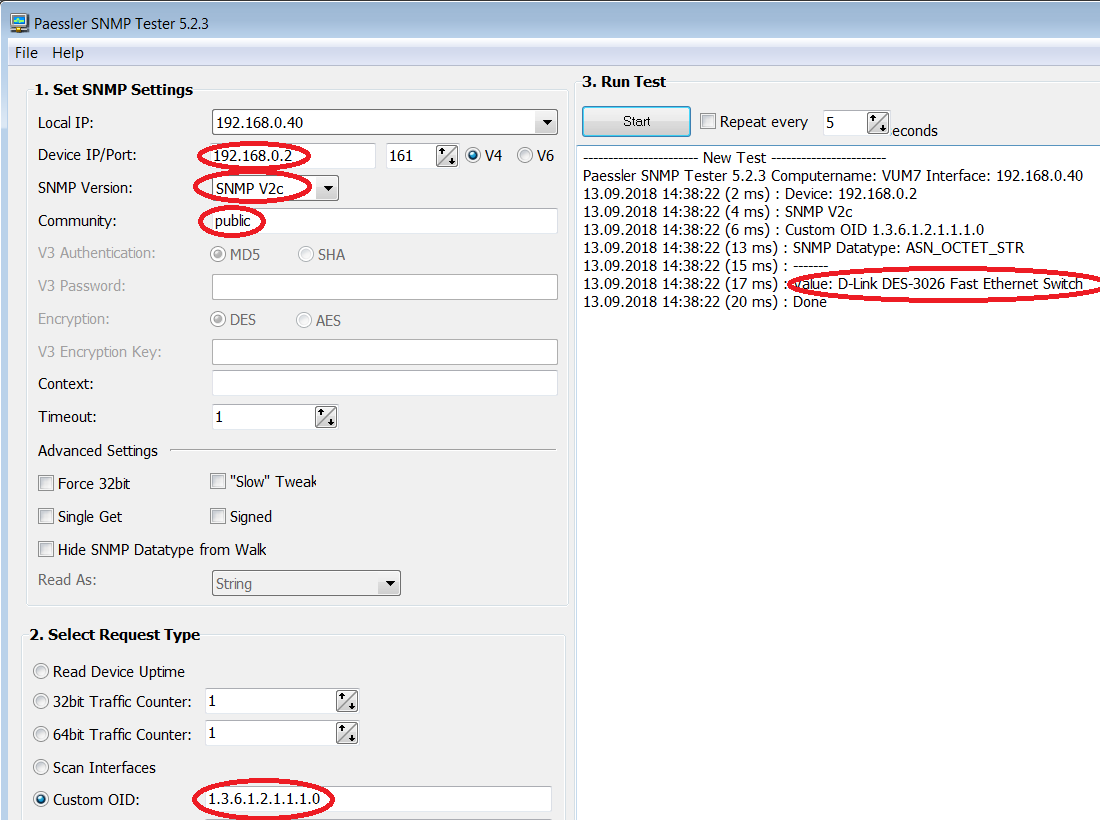
If some of your switches are not discovered then test SNMP access to these switches with any other SNMP utility.
For example https://www.paessler.com/tools/snmptester (see screenshot)
3. Check that all switches are present within the list of discovered devices.
Step 2
1. Click "Collect SNMP data"
Wait until the process is finished.
In case of SNMPv3:
Cisco switches are not typically configured for reading of all the Bridge-MIB information on a
per-VLAN basis when using SNMPv3.
In this case you need to configure an SNMPv3 context as described here:
http://www.switchportmapper.com/support-mapping-a-cisco-switch-using-snmpv3.htm
Step 3
1. Click "Discover the Topology"
Compare the discovered topology with the actual topology.
If necessary use your own connection list to correct the discovered topology.
(Options - Discovery - Edit connection table)
Edit connection table and click "Discover the Topology" again.
2. Click "Apply the New Topology" to save the new topology map.
The discovered topology is shown in the tab "Network Browser".
Subsequently, sometimes it becomes necessary to make changes to the network diagram.
With a small change in topology, it is not necessary to repeat the polling cycle of all
switches, which can take a long time in a large network.
For example, you can quickly add a new switch to the map.
To do this add a new switch to the table at the step 1
Then find on the map the switch to which this new switch is connected,
and in its tools menu select the item "Add new switches here" or
"Discover only the part of the map under this switch"
If you do not know where the new switch is connected, then select any switch on the map,
preferably the last one in the branch and select this menu item. In this case,
you can move the new switch to the desired location using the topology editor,
or it will happen automatically at the next complete rebuilding of the map (steps 2,3).
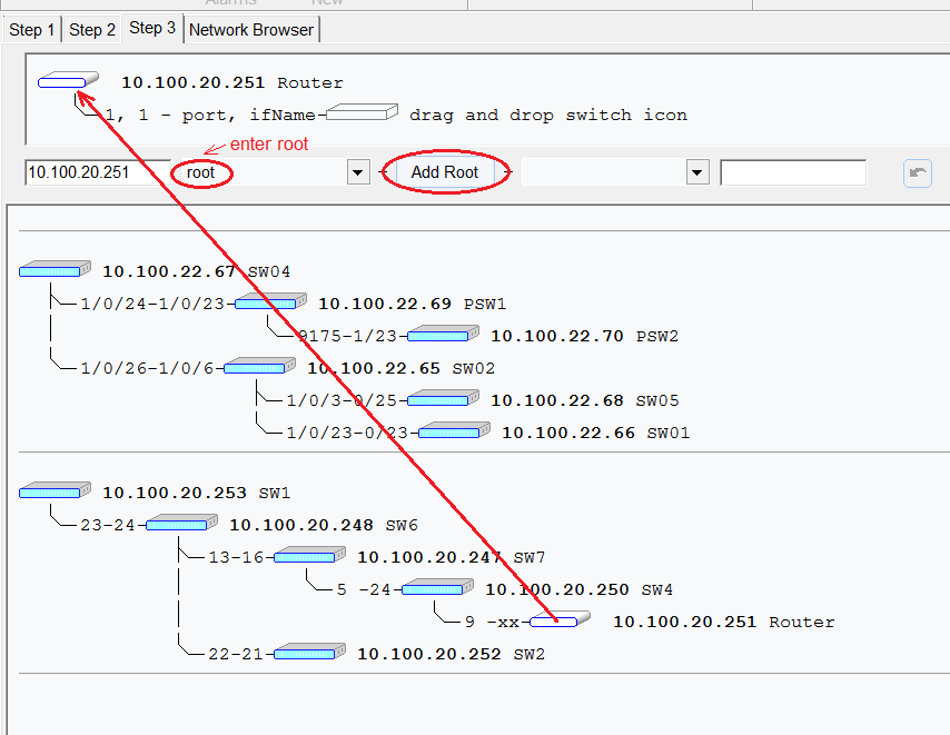
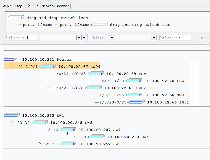
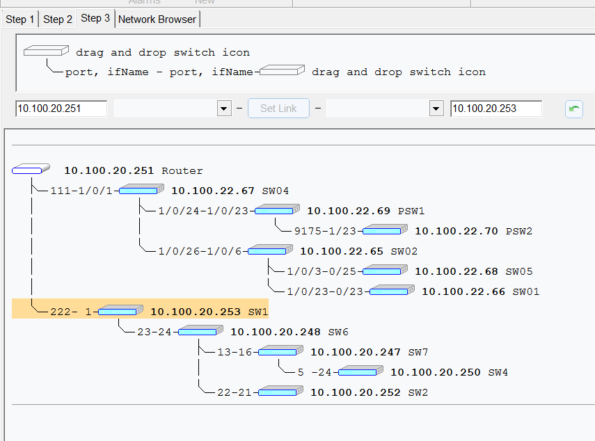
Topology editor
Use topology editor (menu - Service - Edit the Topology) to correct the map.
For example, topology editor allows to make a router as root node.
The screenshots below will help you.